… and Stormwater Too
In the last post, we reviewed a decentralized concept “waste” water management strategy which can render the “waste” water system more fiscally and economically efficient for both the developer and society while also focusing on beneficial utilization of that water resource, rather than on making a perceived nuisance go “away”. In this post, we look at specifically how stormwater can be managed to attain those same ends, as was generally reviewed in “Stormwater Management Can Be ‘Green’ Too”.
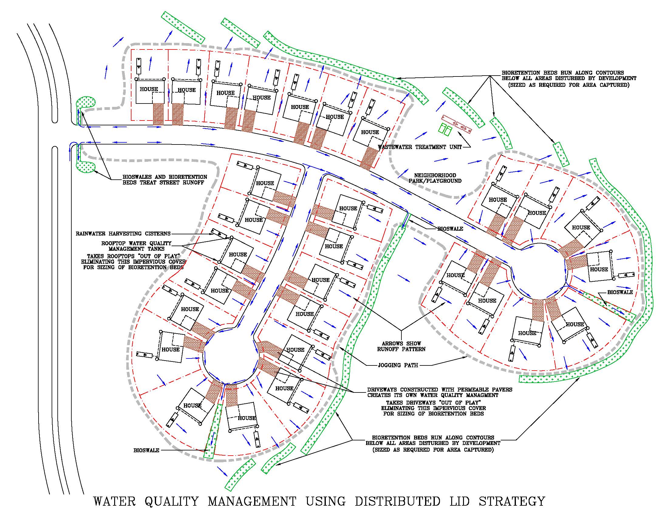
As we did when reviewing “waste” water management, we’ll use that neighborhood in the proposed Headwaters project on the outskirts of Dripping Springs as an example of how we might husband the stormwater resource. A Low-Impact Development (LID) scheme for a stormwater management system is sketched onto the neighborhood plan in the figure below. Two strategies are employed in that scheme, with the aims being to defray demands on the potable water system and to hold at least as much rainwater on the land as would have infiltrated on this site in its “natural” condition:
- Integrate water quality management of runoff from the rooftops with rainwater harvesting to obtain direct use of that runoff to meet irrigation demands over the back yards of each lot.
- Provide water quality management of runoff from the ground level surfaces using bioretention beds, which would retain and infiltrate runoff from the areas tributary to each bed.
[click on image to enlarge]
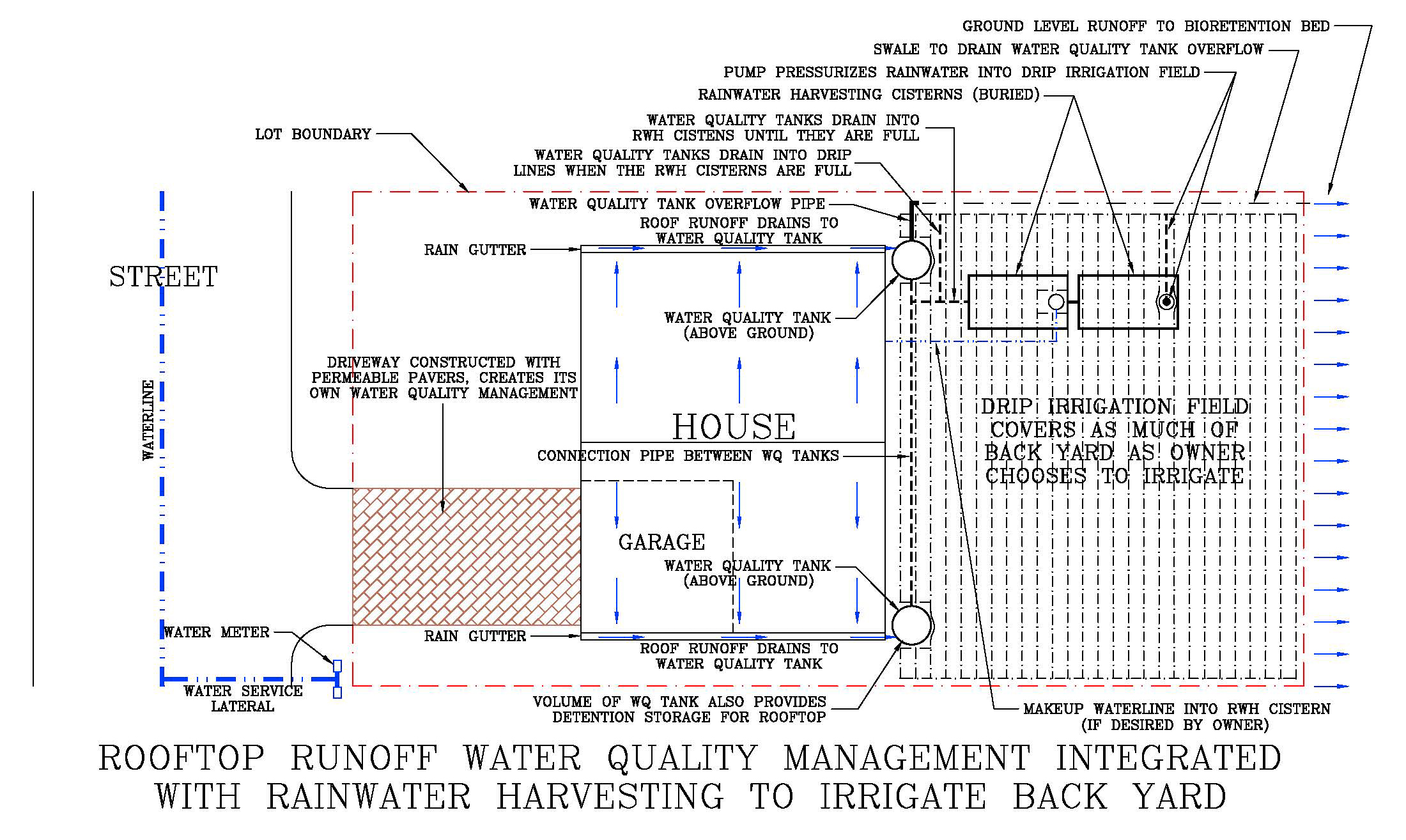
Recall from the last post that reclaimed “waste” water would be used to irrigate “public” spaces – front yards, parkways, a neighborhood park – leaving irrigation of back yards, the “private” spaces, to other means. Under the stormwater management scheme shown above, runoff from rooftops would be captured in a water quality tank integrated into a rainwater harvesting system so that this water could be used to irrigate these back yards. The system integrating these functions is illustrated in the figure below.
[click on image to enlarge]
The rules governing water quality management on this project would require a “water quality volume” (WQV) to be sequestered and treated, while runoff volumes in excess of that amount could overflow and leave the site. The water quality (WQ) tanks shown in the figure above are sized to hold the WQV calculated for the rooftop runoff. The rules require that the WQV must be evacuated within 48 hours, so that this tank capacity is again available to capture that volume from another storm. Typically, under such a scheme, the water in these tanks would be drained “away” over that period and so would not be available to provide irrigation supply, since little if any irrigation would be required within that 48-hour period.
Under the scheme illustrated above, however, these tanks would drain into the rainwater harvesting (RWH) cisterns, which would be buried in the back yard, and only when those tanks were full would water pond up in the WQ tanks. The water in the RWH cisterns could be held there as long as required until needed for irrigation, for which a high efficiency subsurface drip irrigation field would be installed. Thus much of the water that would have been “disposed of” would instead be retained and used to meet irrigation demands.
Note that the RWH cisterns could be installed at the homeowner’s option, required only if the homeowner does plan to irrigate the back yard. If the RWH cisterns were not there, the water quality management concept employing the WQ tanks would still operate in a “normal” mode, as this method is set forth in the applicable rules. As reviewed below, the arrangement shown in the figure above simply enhances that “normal” water quality management scheme.
It does that is by capturing, and retaining on the site, a somewhat larger portion of the roof runoff than would be retained if the RWH cisterns were not there. The WQ tanks would drain into the RWH cisterns until they are full. Typically the RWH cisterns would not be full at the start of most storms, since the typical inter-storm period is long enough that some portion of the water in the RWH cisterns would have been evacuated to run the irrigation system. In that case, the volume captured would be whatever amount is required to fill up the RWH cisterns plus, if that storm produced more than enough rain to fill them, whatever amount ponded up into the WQ tanks, up to the their overflow level. Only the water that had ponded up in the WQ tanks would be drained in short order, with the rest being retained in the RWH cisterns until irrigation was needed.
The majority of the rainfalls over the annual cycle are less than the depth that would generate runoff equal to the WQV and so fill the WQ tanks. Many rainfalls may not even cause water to pond up into the WQ tanks at all, rather all the roof runoff from that storm may flow into the RWH cisterns. Thus a large portion of the rainfall onto the roof would be slowly infiltrated into the soil, through the irrigation system. That water would evapotranspirate rather than flow “away”, just as most of the rainfall over the annual cycle would have infiltrated into the area of soil now covered by the house roof. This greatly blunts the impact of placing impervious cover on the site and so provides a level of water quality protection superior to a system that simply sequesters and releases the WQV within 48 hours, as current rules require. And it does this while also providing a water supply for irrigation. Again, the stormwater management function is integrated with the water supply function, rendering each of them more efficient.
This scheme also proposes that whatever volume does pond in the WQ tanks would drain from them into the drip lines. Knowing the flow rate of the drip emitters at the head created by the ponding depth in the WQ tanks, the number of emitters required to drain the WQV in 24 hours can be calculated, and that many emitters made available to receive this water. Note that this would be done regardless of whether or not the homeowner were to install the RWH cisterns, so that even in that case, the WQV would be largely stored in the soil, enhancing long-term soil moisture, instead of directly flowing “away”.
With this arrangement, draining the WQ tanks in 24 hours, the WQV would also defray any stormwater detention volume that may be required for this project under rules governing the control of peak runoff rates. That would decrease, gallon for gallon, the size of any detention facilities that must be built, another savings for the developer.
As noted, any irrigation system in the back yard would be a subsurface drip irrigation field, fed by a pump in the RWH cistern. This would render the irrigation process most efficient, so that the harvested water would provide as much irrigation benefit as practically attainable. When installed in conjunction with improving the soil to support landscaping in the back yard, a subsurface drip irrigation field would not be significantly more expensive than a less efficient spray system covering the same area. Any installation cost difference would deliver long-term value to the homeowner.
The RWH cistern volume needed so that the back yard could be irrigated with just this water supply can be determined by running a rainwater harvesting model. A fairly cost efficient installation would be two concrete tanks (modified septic tanks), each having a capacity of 2,500 gallons, so that the total RWH cistern volume would be 5,000 gallons. The details won’t be belabored here, but the model will show that, presuming the house roofprint is 2,000 sq. ft. and that the landscaping is composed of plants needing a “low” amount of irrigation, this system would cover the irrigation demands of an area the size of this back yard in all but such severe drought years as 2011 was around here.
About that low water demanding landscaping, if the homeowner wanted a back yard covered mainly with turf, as is often the case – for instance, to provide a playspace for children – then this would urge using the sort of drought tolerant turf offered by Native American Seed under the name Thunder Turf or by the Wildflower Center under the name Habiturf. The irrigation demand profile suggested by these bodies to maintain this turf in a fairly lush condition was presumed in running that rainwater harvesting model. To whatever extent turf would be displaced with shrub beds, ground cover, etc., these plants also should be drought-tolerant natives. This illustrates the need to move to more regionally appropriate landscaping as an overall part of water management strategy here.
Before proceeding to consider the general strategy for managing runoff from ground level surfaces, note an optional “wrinkle” suggested in the figure above for managing driveway runoff. If driveways were constructed using permeable pavement, in essence they would create their own water quality management system. The rain falling on the driveway would not run off, rather would infiltrate through the pavement surface, to be held in a gravel bed below until it infiltrated. That bed would be sized to hold at least the WQV calculated for the driveway pavement area. Until that bed filled up, no runoff would flow “away”. Again, over the annual cycle a majority of the rainfalls have a depth less than the WQV capture depth, so would not produce runoff from this pavement. This impervious surface then would have a rainfall-runoff response somewhat similar to the area of natural soil it displaces.
The driveway pavement could be composed of pavers, porous asphalt, or porous concrete. Being a fairly small area of pavement, any cost bump over a “normal” concrete driveway – the typical installation – would be “small” for each home. This would be defrayed by there being less impervious surface draining to the other ground level stormwater controls, decreasing their sizes, and thus their total costs.
A variation of this would be to make the driveway a rainwater harvesting system as well, by installing material below the pavement that would hold a significantly greater volume than the calculated WQV. This could be done by installing a deeper gravel bed to create more void volume. However, there are a number of products on the market made just for the purpose of creating a water storage volume below a paved surface which may provide this storage more cost efficiently. This stored water could also be used to defray irrigation needs.
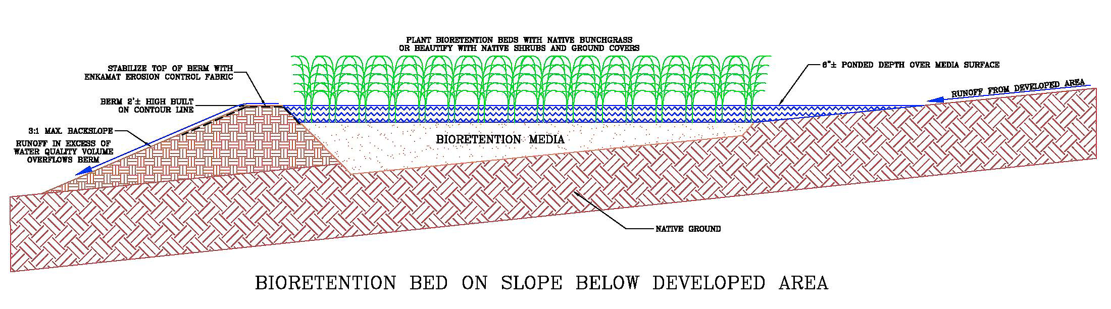
Now to the management of stormwater runoff from ground level surfaces. As shown on the overall development plan above, bioretention beds would be built downslope of all developed areas. These beds would intercept and treat an amount of runoff from each storm up to the WQV calculated for the area tributary to each bioretention bed, and would also infiltrate that WQV. The general scheme for construction of the bioretention beds is shown in the figure below, on this particular site taking advantage of the sloping ground on which those beds would be arrayed.
[click on image to enlarge]
The berms built to contain the bioretention beds could use material excavated on the project site for roads and house foundations, providing both on site “disposal” of this spoil and a cost efficient source for that material. The core of the berm could be the poor quality subsoil, while the top and downslope surfaces of the berm would be covered with salvaged topsoil so that those surfaces could be effectively restored to prevent erosion. All such disturbed surfaces on the project site would be restored with native grasses and/or wildflowers so that no long-term irrigation of those surfaces would be needed. The bioretention bed surfaces would also be restored with native plants, chosen to endure both short-term inundation and long-term dry spells. With good planning, these plants would enhance and blend in with the vegetation on the slopes below the developed areas to provide a pleasant viewscape from the house yards.
A bioretention bed stores the WQV until it can be infiltrated into the soil below it. A combination of the void volume in the bioretention media and a ponded depth above the media provides this storage. The minimum required footprint of the bioretention bed is determined by the infiltration rate of the soil underlying the bed. The height of the berm would be set so that the bioretention bed surface would run far enough up the slope to provide the required area. Any runoff into the bioretention bed in excess of the WQV would overflow the berm, either as sheet flow or through defined overflow weirs, in which case provisions would have to be made to avoid erosion due to those channelized flows.
By capturing and infiltrating the WQV in these bioretention beds, we would be holding on the land at least as much rainfall as would have been infiltrating under the “natural” condition of this land. The way these beds would be constructed, they could be rather cost efficiently “oversized” relative to the calculated WQV to retain more runoff. It would indeed be good to hold more rainfall on the land, since the “natural” condition of this particular property is rather hydrologically degraded, the legacy of poor land management practices by previous generations. This scheme for stormwater quality management can thus help to “heal” the land as well as provide superior water quality management. This strategy will greatly blunt the degradation of water quality over this watershed that the placement of development on this degraded landscape could readily impart.
Another benefit of this scheme is that, with the thin soils covering this landscape, much of the water that infiltrates below the bioretention beds would probably not be retained in the soil over the long term, rather it would migrate to rock shelves or other slowly permeable strata and move downslope, where a significant portion of it may emerge at seeps. This is why it is important to provide the high level of pretreatment that a bioretention bed can impart, which along with migration through the soil will deliver a highly “renovated” water to the seep faces.
This is a benefit because these seeps could flow into streams, increasing and extending baseflow in the creeks downstream. That would benefit the riparian environment generally, but in this particular area, it could provide another benefit. The creeks which drain this area run through the Recharge Zone of the Edwards Aquifer, and in creek beds are where a large majority of this aquifer’s recharge occurs. Understand that under a conventional stormwater quality management scheme, which focuses on making the runoff flow “away” after short-term detention, adding impervious surfaces would make creek flow more subject to “flash” hydrology, with a large flow surge following a storm and then no flow between storms. Those large flow surges would more readily flow on by recharge features in the creek beds, and so would less “efficiently” recharge the aquifer. Therefore, extending the period of flow at a lower rate – that is, enhancing baseflow at the expense of quickflow runoff – would enhance recharge, and so enhance the water supply obtainable from this aquifer.
As for the cost efficiency of this strategy, notice in the overall neighborhood plan there are no storm sewers. Indeed, flows would only be channelized in the street gutters, flows which are directed into bioretention beds where they are spread out and infiltrated. It has been typically observed that this sort of stormwater management concept, centered on distributed green infrastructure rather than gathering runoff into more centralized end-of-pipe devices, is significantly less expensive, even as it does a better job of water quality management. Add on the water supply value the suggested scheme provides and this approach is no doubt significantly more cost efficient, both directly for the developer and globally for society.
In summary, this stormwater management strategy of integrating rooftop runoff with rainwater harvesting and capturing, treating and infiltrating ground level runoff provides superior water quality protection while also augmenting water supply. Overall, just as for the “waste” water management strategy reviewed in the last post, this integrated stormwater management strategy offers a win-win-win for society, for the developer, and for the residents of this project. It is another aspect of the sustainable water strategy that should be considered for all development in this region.
Explore posts in the same categories: Uncategorized

October 15, 2014 at 3:59 am
Excellent information! Significant reductions in outdoor uses, resulting from homes and businesses that are designed, and built for areas with known water availability problems and concerns about water pollution, could well eliminate the need for massive new water supply projects. Water conservation and water quality would be enhanced through Low Impact Development strategies and techniques that when employed, will keep water from rapidly running off of the land it typically passes over and is lost. Both critical issues affecting the Texas Hill Country and major population centers such as San Antonio and Austin along the I-35 corridor. Keep up the good work. Someday, the builders, bankers, engineers and consumers will get the message and policy makers will react.
October 15, 2014 at 6:47 am
Thanks, Milan. Absolutely correct. Let’s just hope that “someday” is soon.